USRP Upgrade for High Frequency 5G Millimeter Wave Solution
POSTED ON JANUARY 4, 2022 BY TMYTEK
Overview
Universal Software Radio Peripheral (USRP) devices are software-defined radios (SDR) used for RF applications. USRP transceivers can transmit and receive RF signals below 6 GHz, and you can use them for applications in communications education and research. USRP is suitable for a variety of applications, including 5G wireless communication research, radar exploration, algorithm development, etc. for wireless signal transmission and reception analysis.
However, USRP does not support the commercialized higher frequency 5G millimeter-wave (mmWave) communication technology, and the price of buying a new mmWave instrument may cost more than 300,000 US dollars, which is very expensive. We began to think about whether we have the opportunity to use the existing USRP with mmWave upgrades so the existing instruments can be utilized, while costs remain economical. For the existing USRP users, the original software development resources can continue to be used, making this an advantageous upgrade plan.
TMYTEK believes that the high cost and difficulty of obtaining mmWave instruments pose a barrier to the research of mmWave. The mmWave solution upgrade for USRP we recommend can solve the pain points for researchers. By using existing low-frequency instruments to upgrade to a mmWave solution, mmWave researchers can establish a laboratory environment for rapid research, help promote and realize the popularization of mmWave 5G communication, at an economical cost and in a shorter time frame.
Concept
As shown in Figure 1 below, a complete mmWave system is divided into three parts, namely the baseband, up-down converter and beamformer. Different from the sub-6 communication system, you will find that the beamformer is integrated into the entire communication system architecture. The reason is that when we use the mmWave frequency band as the communication frequency, the signal attenuates in the air very quickly and this will require the use of beamforming technology to increase the signal strength. Therefore, the beamformer is a necessary part of the mmWave communication.
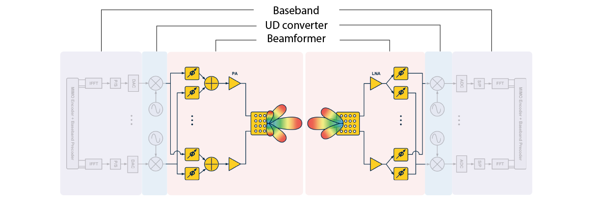 Figure 1. Architecture of mmWave system
The beamformer is also called an Antenna-in-Package (AiP), which is an antenna that can beamform in a specific direction. It usually includes an array antenna, PA, LNA, switch and phase shifter. According to the electromagnetic wave theory, by adjusting the phase output of the antenna element, we can generate the maximum electromagnetic wave energy transfer in a specific direction. This is the principle of beamforming, as shown in the figure below.
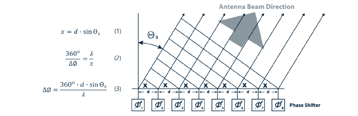 Figure 2. Principles of beamforming
Please note the USRP architecture diagram (Figure 3), and compare it to Figure 1. You will find that the USRP can be used as a complete baseband hardware, and the RF port of the USRP at this time will be the intermediate frequency (IF) port of our mmWave instrument. We use UD Box as a secondary up-down converter. After the up-down conversion of the intermediate frequency signal to the mmWave band, plus the beamformer, it becomes a complete mmWave hardware architecture.
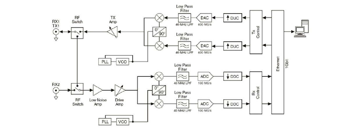 Figure 3. USRP architecture diagram.(Source: NI)
But just functionality alone is not enough, we also need to confirm the signal quality of the receiving and transmitting end of the mmWave system to ensure it can be used in various research and development processes. Here, we need to employ the Error Vector Magnitude (EVM) as a signal quality indicator.
The EVM is a measurement used to quantify the performance of a radio transmitter or receiver. A signal sent by an ideal transmitter or received by a receiver would have all constellation points at the ideal locations. However, various imperfections may cause the actual constellation points to deviate from the ideal locations. The EVM is a measure of how far the points deviate from the ideal locations. Noise, distortion, spurious signals, and phase noise all degrade EVM. Therefore, EVM provides a comprehensive quality measurement of the radio receiver or transmitter.
Methodology
According to the concept mentioned previously, we will use the USRP with TMYTEK's UD Box and Box for actual construction and testing. As shown in Figure 4 below, the instruments needed are:
● NI USRP X 1
● TMYTEK dual channel UD Box X 1
● TMYTEK BBox One X 1
● TMYTEK BBox Lite X 1
● SMA RF cable X 2
● High frequency RF cable X 2
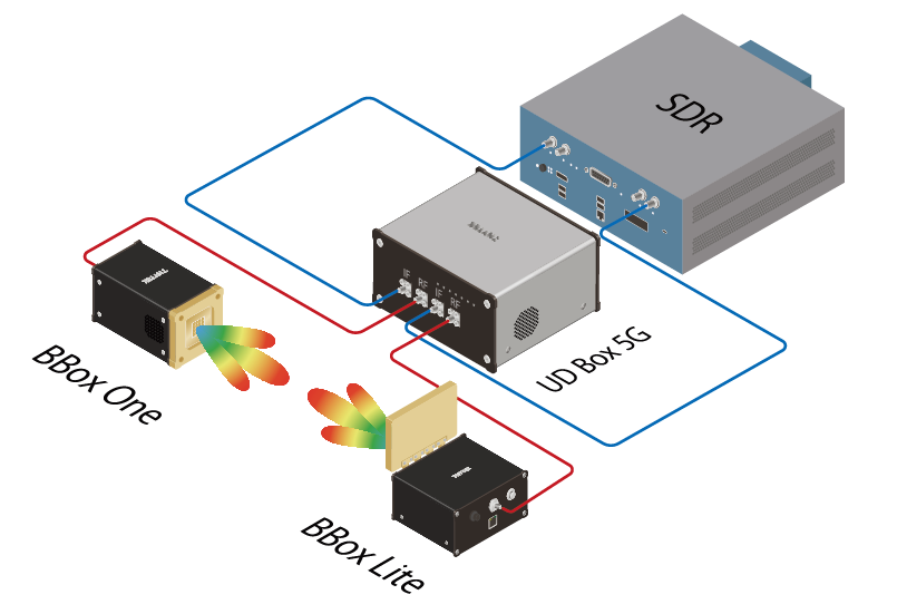 Figure 4. USRP upgrades mmWave system
Step-By-Step
Step 1: Hardware installation
As shown in Figure 5 below, the dual channel UD Box has 4 ports, two IF and two RF ports. Here, we regard the USRP as an RF intermediate frequency signal, so we connect the transmitting and receiving end of the USRP to the IF port of UD Box respectively. It is worth mentioning here that since our UD Box 5G is bidirectional, there is no need to pay attention to which port is connected to Tx and which port is connected to Rx.
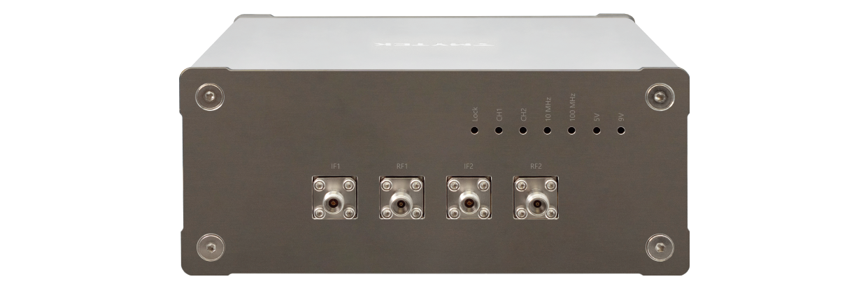 Figure 5. UD Box 5G dual channel
Next, we connect the two RF ports of UD Box to the RF COM Ports of BBox One and BBox Lite to complete the basic hardware architecture connection. Finally, we connect the Ethernet ports of UD Box and BBox to the controller computer (UD Box and BBox are both controlled by Ethernet). As shown in Figure 6 below, once all devices have turned on, you may download and install TMYTEK’s TMXLAB Kit (TLK) software to configure settings using the graphical user interface.
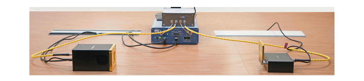 Figure 6. Hardware setup
Step 2: Software installation
Go to TMYTEK’s official website, download the TMXLAB Kit control software, and install it on a Windows PC.
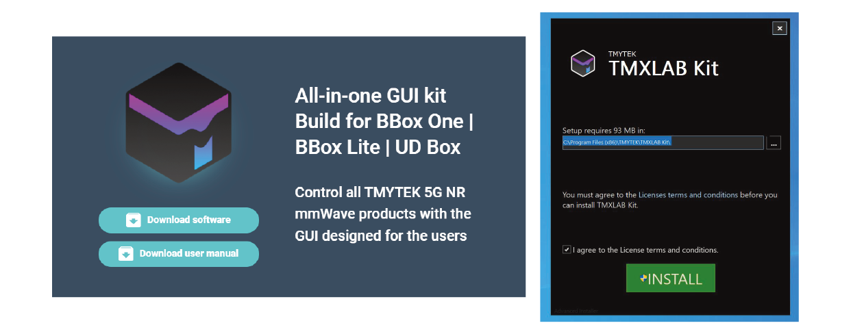 Figure 7. Download website and installation screen
Once the installation is complete, run the TMXLAB Kit to configure the hardware instruments. Here, we do not need to run multiple configuration windows because TMXLAB Kit can control and configure multiple UD Box and BBox devices, as shown in Figure 8.
 Figure 8. Screenshot of TMXLAB Kit menu bar
 Click on the UD Box icon in the “Scan Local Device” to enter the UD Box configuration settings, as shown in Figure 9.
 Figure 9. Click on the UD Box icon
As shown in Figure 10, we need to confirm that the Lock signal is on (lit up red), which means that the PLL of UD Box 5G is locked. We then configure the RF frequency (transceiver frequency of BBox), IF frequency (transceiver frequency of USRP), LO frequency (here we can choose High-Side injection (HIS) or Low-Side injection (LSI) *1) and bandwidth*2, then click on the Save button to save the configurations. In addition, our UD Box advanced settings will be explained in legend *3.
*1 Since the frequency range of LO and RF are both 24 - 44GHz, when RF is set at the maximum and minimum values, it may only be possible to use single-sided injection.*2 This setting helps us to calculate whether there will be harmonic interference, and a yellow font will be used for warning when interference occurs.*3 Ref Source: 100 MHz clock source, Channel Control: on/off, Ref Control: clock on/off, Output Voltage: on/off.
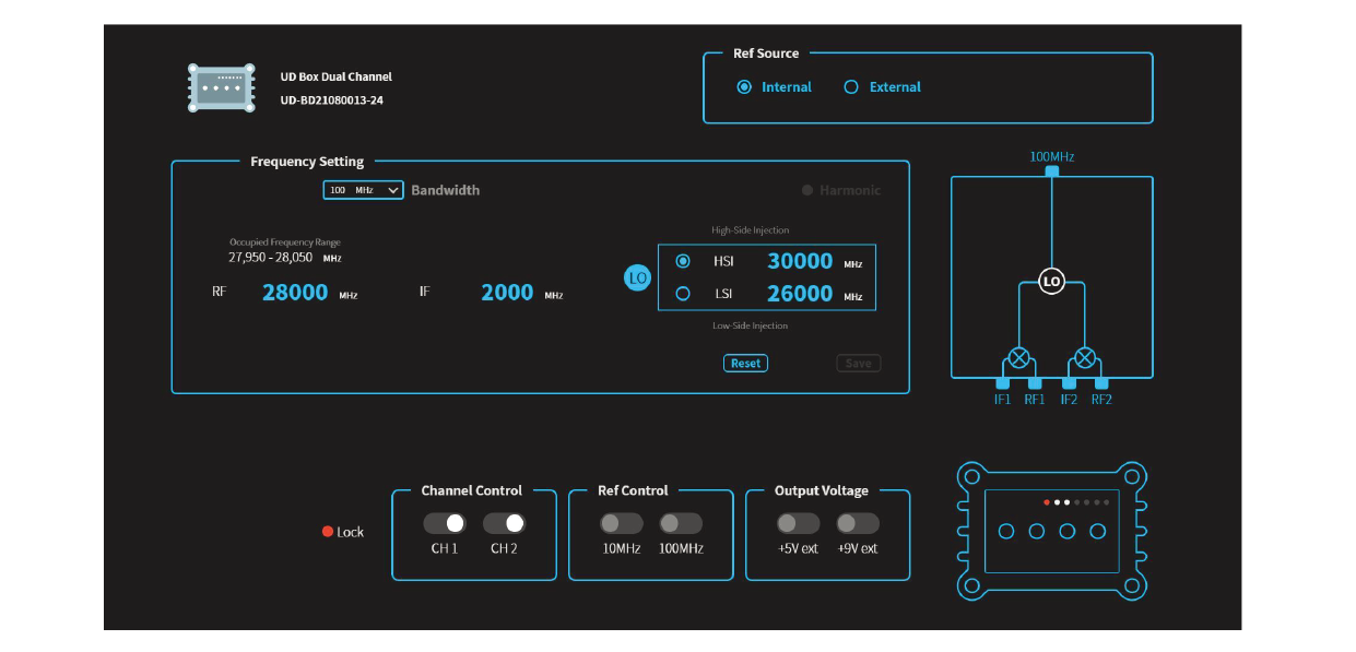 Figure 10. Screenshot of UD Box control interface
Then we continue to set up BBox One and BBox Lite. We will set BBox One as the transmitter and BBox Lite as the receiver.
Click on the BBox One icon in the “Scan Local Device” to enter the BBox One configuration settings, as shown in Figure 11.
 Figure 11. Click on the BBox One icon
After entering the setting screen of BBox One, select TX mode, and configure the center frequency and import default antenna parameters, as shown in Figure 12.
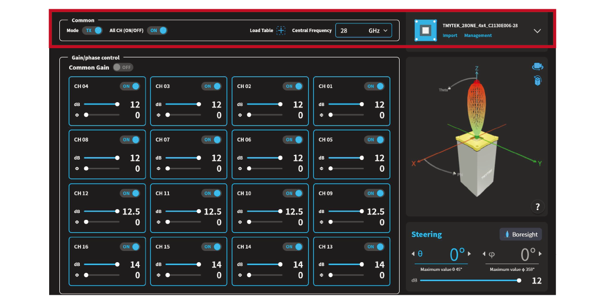 Figure 12. Screenshot of BBox One control interface
Click on the BBox Lite icon in the “Scan Local Device” to enter the BBox Lite configuration settings, as shown in Figure 13.
 Figure 13. Click on the BBox Lite icon
After entering the setting screen of BBox Lite, select RX Mode, and configure the center frequency and import the default antenna parameters, as shown in Figure 14.
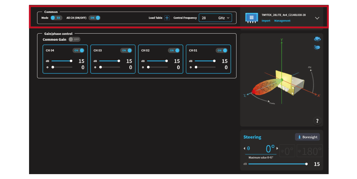 Figure 14. Screenshot of BBox Lite control interface
Now that we have completed all hardware and software settings, the USRP has been upgraded to a mmWave test instrument, we can start using the USRP for testing.
Test Case
The following section will demonstrate the signal measurements of the system.
We begin by starting up the USRP transceiver to see the signal quality after integrating the up-down converter and beamformer. To do this, we ran the LabVIEW Communications, created a template under the project name “LTE Design USRP RIO v19.5” (as shown in Figure 15), and click on Create.
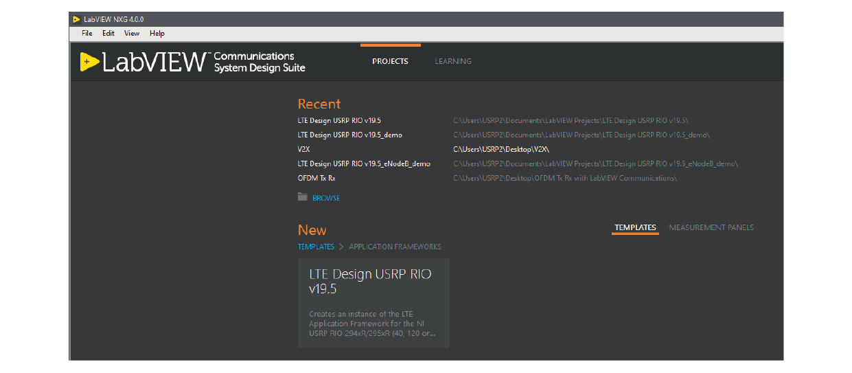 Figure 15. Screenshot of LabVIEW Communications
The operation screen of the LTE Application Framework should appear (as shown in Figure 16). Here, set the USRP “RF TX Power” to 5 dBm, after the signal attenuation of the up-down converter, the signal gain of the BBox, and the attenuation in the air, the signal strength is about -35 dBm. We found that both the constellation diagram and the EVM indicated good signal strength.
Once we have measured and confirmed that the signal is ready, we can then use TMXLAB GUI to control the beamforming angle of the BBox, observe and record the changes in signal strength and EVM.
In the initial state here, there is an angle of 0 degrees between the transmitter and the receiver, and the GUI is also set at 0 degrees, as shown in Figure 16.
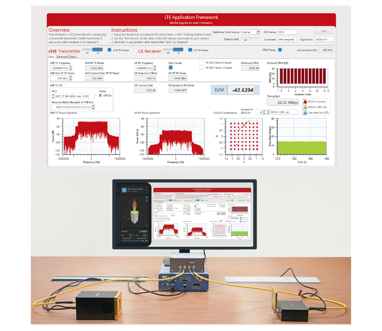 Figure 16. Signal measurement under conditions: the placement of BBox One is 0 degree and beam direction of BBox One is 0 degree
If we turn the transmitter -30 degrees, we will find that the signal strength becomes weaker, and the EVM measurement also worsens, as shown in Figure 17. This is because the energy of the transmitting end is not directed towards the receiving end. This is not an ideal state for wireless communication. Therefore, we use the beamformer to change the launch angle of the transmitter, and the signal strength and EVM measurements are restored to the original signal quality, as shown in Figure 18.
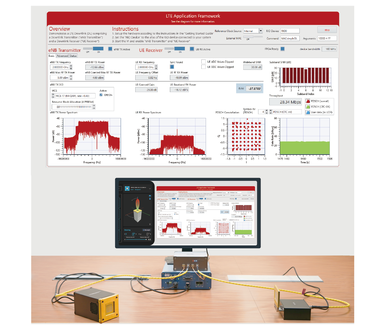 Figure 17. Signal measurement under conditions: the placement of BBox One is -30 degree and beam direction of BBox One is 0 degree
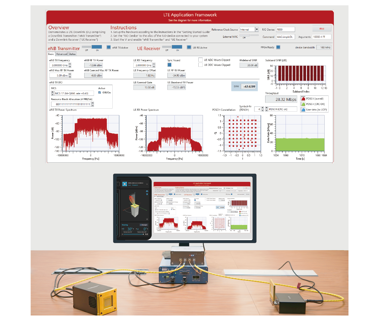 Figure 18. Signal measurement under conditions: the placement of BBox One is -30 degree and beam direction of BBox One is 30 degree
Summary
With this simple demonstration, we have proved that such a mmWave upgrade solution is feasible and has good signal quality. In addition, we can also use the beamformer to change the angle to improve the quality of wireless communication. We can utilize this set of mmWave equipment to simulate the problems that 5G communications may encounter, such as beam management, beam algorithm, channel sound, etc.
Download USRP Upgrade for Hight Frequency 5G Millimeter Wave Solution Application Note >>